|
About 4 years ago I built a rather complicated 24 channel DMX to Analogue converter. Since that time quite a few people have asked me if I can put the details online and make the PCBs available. Unfortunatly I lost the PCB designs, and the circuit was, to be honest, more complex than it needed to be, with keypads, and LCD displays to make it programmable.
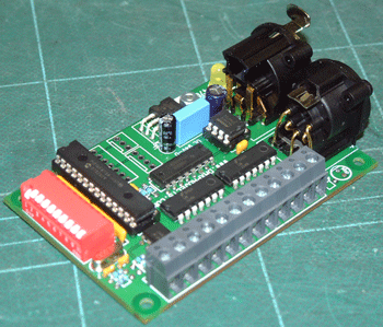
In response to all the people that have asked about it, I decided to design a simple DMX to Analogue demux. Its has 8 onboard analogue outputs, and expansions connectors to allow for an additional 56 outputs on an, as yet undesigned or built, expansions board.
I have decided to sell this module ready made, rather than as a kit. As such I have not put the constructions details, or schematic online.
|
| |
| | |

| | |
| | | |
DMX Analogue module
| | |
|
DIP switch configuration
| 1 |
2 |
4 |
8 |
16 |
32 |
64 |
128 |
256 |
Inv |
The first 9 DIP switches set the DMX start addess in binary. Simply add the value of the switches to get the start address, for example to use a start address of 58 you would set DIP switches 32, 16, 8 & 2 to ON, leaving 256, 128, 64, 4 & 1 OFF.
The last DIP switch is the inverse setting. When off, a DMX value of 0 will result in 0v on the relevant output, and a value of 255 will result in 10v on the output. When the Inverse switch is set to ON, then a value of 0 will result in 10V being output, and a value of 255 outputs 0v.
The DIP Switches are constantly read, so any changes made will be reflected on the outputs in real time.
|
This module requires a 12 to 24v DC power supply, and has 8 x analogue outputs, 1 x 10v reference output. There is a PCB mounted LED (this can be exchanged for a 2 pin PCB header if required for fitting your own case mounted LED). The LED will give a dim light when power is applied, and a bright light when DMX is detected.
This module comes with either 5 pin PCB mounted XLR connectors, 3 pin PCB mounted XLR connectors, or 2 x 3 pin PCB headers for connecting to your own XLR connectors. Please specify the required connectors when ordering.
PCB Connectors (left to right, starting at the DIP switch end of the PCB)
| Vin |
0v |
0v |
Vref |
Ch8 |
Ch7 |
Ch6 |
Ch5 |
Ch4 |
Ch3 |
Ch2 |
Ch1 |
Vin should be a standard regulated DC power supply between 12 and 24 volts.
Vref is a 10V reference output. This can be used with inverted mode to get negative channel outputs.
Ch1 - Ch8 The analogue channel outputs. These are short circuit protected by LM324 OpAmps, and can supply upto 20mA each.
|